CARMA provides 2 VLBI stations:
- 8 antennas are phased together in a set of beamformers and recorded on one Mk6 recorder.
- a separate 'reference' antenna is connected to a standard BDC and R2DBE and is recorded on a separate Mk6 recorder.
The exact LO1 frequency for the 2015 experiment is:
f(LO1) = 3 * (7 * (9 * fsynth - 10 MHz) + 50 MHz)
       = 221099.999970 MHz (for fsynth = 1170.158730 MHz)
A diagram of the CARMA IF system is shown below. The signals for the reference antenna are taken from wideband directional couplers in the fiber IF receiver boxes; these 1-9 GHz bands are sent to standard EHT block downconvertes and R2DBEs. The signals for the beamformers are taken from the outputs of the CARMA analog downconconverters.
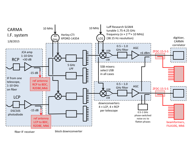
Note that the signals sent to the beamformers undergo a total of 4 downconversions before they are sent to the recorders:
- sky signal mixes with LO1 (221.1 GHz) to produce IF1 [USB}
- IF1 mixes with 10 GHz in block downconverter to produce IF2 [LSB]
- IF2 mixes with LO2 to produce IF3 (500-1000 MHz) [USB]
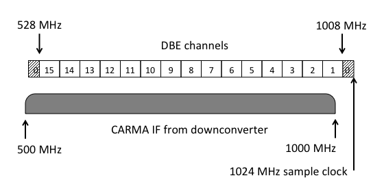
- IF3 is digitized with 1024 MHz clock and split into channels as shown in DBELayout below [LSB]
The LO2 frequencies are band1 = 3930, band3 = 3450, band5 = 2970, band7 = 2490. These are the CARMA band numbers -- there are 8 independent bands for single polarization observations at CARMA, but for full polarization observations the bands are paired (1 and 2, 3 and 4, 5 and 6, 7 and 8) and a single 2nd LO is split between each pair of downconverters.
The DBE layout is shown below. It is the same as was used in 2013. Channel 0 is recorded on the disks (I have never understood why, since it seems to be useless).
The sky frequencies corresponding to these channels are shown in the diagram below ("caseD"). Channel 0 is not shown since it is useless. Channel 1 is not shaded because it includes frequencies > 1000 MHz that are cut off by the 500-1000 MHz filter in the CARMA downconverters. Channel 1 should provide useful data, but its gain will be lower than the other channels.
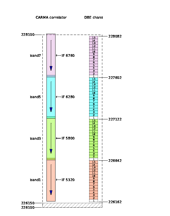
Below are some numerical examples to help make clear the channelization for the beamformed antennas:
Example 1:
sky signal = 226162
IF1 = 226162 - 221100 = 5062
IF2 = 10000 - 5062 = 4938
IF3 = 4938 - 3930 = 1008
IF4 = 1024 - 1008 = 16 (lower edge of DBE chan 1)
Example 2:
sky signal = 226194
IF1 = 226194 - 221100 = 5094
IF2 = 10000 - 5094 = 4906
IF3 = 4906 - 3930 = 976
IF4 = 1024 - 976 = 48 (upper edge of DBE chan 1)
Example 3:
sky signal = 226642
IF1 = 226642 - 221100 = 5542
IF2 = 10000 - 5542 = 4458
IF3 = 4458 - 3930 = 528
IF4 = 1024 - 528 = 528 (upper edge of DBE chan 15)
also...
IF3 = 4458 - 3450 = 1008 in band 3
IF4 = 1024 - 1008 = 16 (lower edge of DBE chan 1 in bands)