Synthesizer module: installation and test
From $1
- You do not have permission to set restrictions on this page.
Cabeling
- Connect your 10MHz signal to the backside 5/10MHz pin
Test procedure
- Power on the clock module.
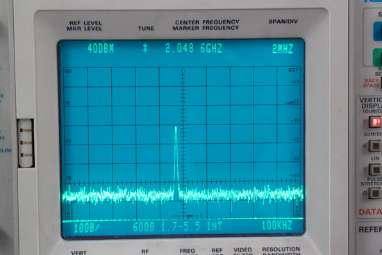
- Connect one of the frontside pins labeled 0-3 to a spectrum analyzer. Verify that you see a line that is peaking at 2048 MHz.

- Check the peak power level. The frontside pins labeled 0-3 provide the clock with decreasing power levels. Select the pin that gives a power level in the targeted range (0 to -3dBm)
- Connect the selected pin with the "clk" pin on the frontside of the R2DBE.
Open questions
- What is the procedure if only 5MHz is available at a station?
- Is the 0 to -3dBm power level correct? (Only took this number from private com.)
| Images 1 |
|---|
 | | |


