Cabeling
- Connect USB cable to a computer preferably running Windows (only needed for first time setup)
- Connect the ethernet cable to your local network
- Connect the backside pin labeled "Tone In" to a signal generator
Setup
- Connect your Windows PC via USB
- On your PC install the "mini-circuits RF switch software" (http://194.75.38.69/softwaredownload...ller_Setup.zip)
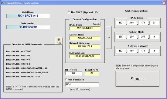
- Open the "mini-circuits RF switch software" and press the "USB" button. Then hit "Ethernet config"
- Uncheck the DHCP option. Assign a static IP-address. Note down the IP-addres.
Testing
- Connect one of the four (module A,B,C,D) frontside pins labeled "COM" with a spectrum analyzer.
- On your external signal generator produce a line at any place in the 0-2 GHz regime.
- Using the mini-circuits software: For the module that you have connected to your spectrum analyzer switch to the "COM->2" setting. A red line should be displayed that connects the pins "COM" to "2".
- On your spectrum analyzer select the band 0-2.5 GHz. You should see something like the following: the bandpass should be flat from 0-2GHz. Check that the line appears at the right position.
Open questions
